High-speed-directional control valves
Valve Functional Test Rig
Product details:
Test rig for the measurement of 2/2-high-speed-directional control valves.
This test rig is used for the measurement of 2/2-high-speed-directional control valves. The switching procedure is tested by means of the closing and opening time and the switch-on and switch-off current. Furthermore, the maximum flow rate is measured at a controlled pressure difference. All measurements can be performed in both flow directions in a temperature range between 20 °C and 120 °C.
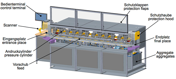
Construction
The test rig is designed as a modular system and can be reconfigured according to requirements. To achieve the highest possible throughput, the test rig is divided into stations. Every station (infeed station, measuring station, leakage station) has four places, a transportation system and an own automation which is connected to the central control computer via the real-time Ethernet network EtherCAT. The measurement results of a test are individually assigned to the test items. The data is then stored on the test rig server and is available in the company network for further processing.
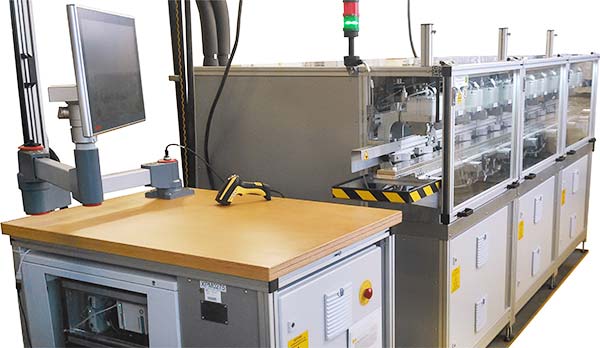
The test rig comprises the hydraulic supply, the electrical control of the test items, the handling of the test items as well as the measurement and control technology.
Following tests are designed with different measuring methods for the test rig:
- endurance test conditioning
- switching times via current progression
- switching times via laser vibrometer
- volume flow
- leakage
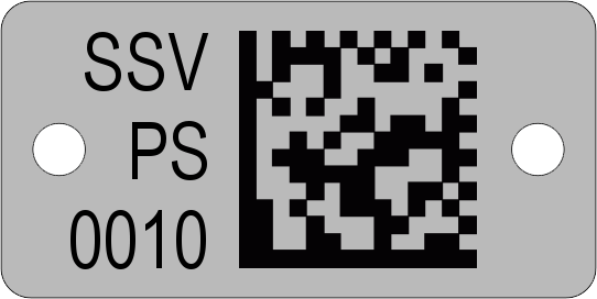
Test Item Identification
All test adapters are equipped with an individual 2D code (DataMatrix code), which is read by a camera system.
The 2D code is captively connected to the test adapter.
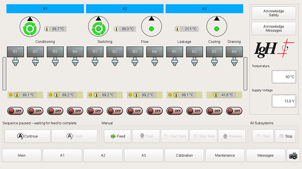
Measurement Data Evaluation and Recording
During the measurements a lot of data is collected in a short time. The recording starts automatically as soon as the pressure cylinder has pressed a test adapter. In addition to the process data, a signal is recorded which indicates the range of measurement data used for automatic evaluation.
Each test station starts its own data recording, which the server can process simultaneously with different cores. When a measurement is finished, an evaluation program starts which calculates relevant results from the data stream and stores them in the database.
Technical data:
| electrical installed power: | 25 kW |
|---|---|
| tare weights (stations): | A1 = 653 kg A2 = 788 kg A3 = 696 kg |
| dimensions: | L = 3600 mm + 780 mm W = 1450 mm H = 1670 mm |
| max. supply pressure (pneumatic): | 7 bar |
| max. operating pressure (hydraulic): | 95 bar |
| temperature range hydraulic components: | 20 °C – 120 °C |
Your contact persons:

| Dipl.-Ing. (FH) Florian Pose | |
|---|---|
| Phone: | +49 (0)2 01 – 3 60 14-0 |
| E-Mail: | |

| Dr.-Ing. Siegfried Rotthäuser | |
|---|---|
| Phone: | +49 (0)2 01 – 3 60 14-0 |
| E-Mail: | |